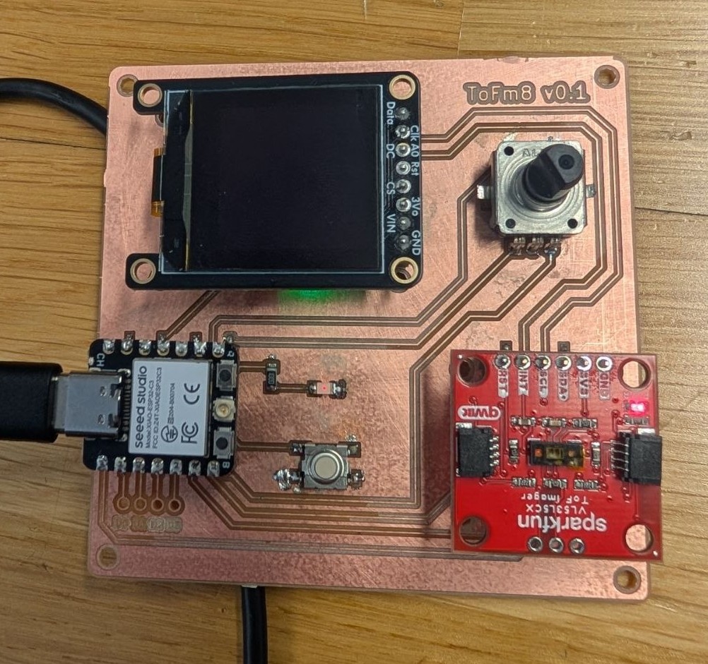
ToFm8
A prototype of a tool for troubleshooting and calibrating the Sparkfun VL53L5CX ToF Imager.
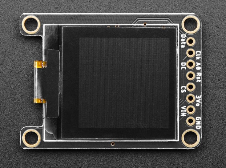
For one of Digital Fabrication assignments we had to make a board that utilizes input/output devices. For input I decided to try out the Sparkfun VL53L5CX ToF Imager which I had at home. It's a depth scanner / 3d mapper with up to 64 zones. In the Physical Computing course I used two distance sensors to measure the angle of my hand, I want to see if I can get away with one.
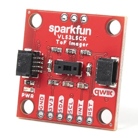
For the ouput device I picked the Adafruit Monochrome 1.12" 128x128 OLED, which I also had at home. It makes a nice pair because the resolution is double the number of max zones on the VL53L5CX. My idea was to make a debugging tool where I can see visually how the zones are operating, this way it'll be easier to calibrate the sensor for my needs.
CONNECTIONS
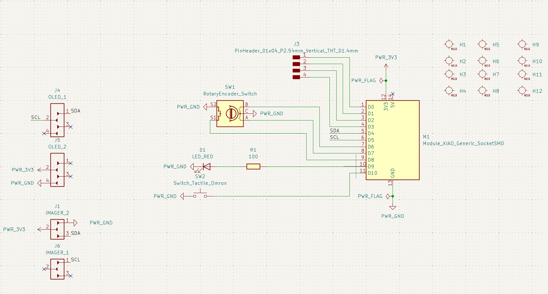
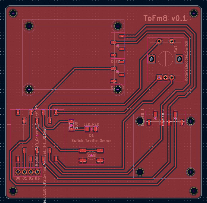
I also added a push-button encoder (to change settings, menu-dive etc.) and a button + red LED light (as transmission on/off button, so that the distance sensor only works when you want it to and doesn't accidentally send data when your elbow passes over it). I decided to have the OLED on the top left of the board and the sensor on the bottom right, so that you can still see the screen when your hand is close to the board. Aesthetically it would be more pleasing to have them both centered horizontally, but you can't have it all!.
To make the connections work neatly on the board I decided to forego the first four pins (D0-D4) and use the ones on the other end. This would end up biting me in the ass. The data for the input and output devices is sent by the SCL and SDA wires, where the devices are daisy-chained.
I dubbed my project the ToFm8 or Time-of-Flight Mate. I had a lot of troubles milling the board, which I won't get into now, but I am happy that I correctly measured the mounting hole positions for my components on the first go.
CODE
For this project I decided to stick with the Arduino IDE (and thus C), as there weren't direct libraries for these components on MicroPython. It would have potentially required quite a bit of fiddling around with some kind-of-compatible libraries.
Let's start with the VL53L5CX. To get it working you need to include the library (obviously) and create two objects, SparkFun_VL53L5CX (let's dub it myImager) and VL53L5CX_ResultsData (data class structure for the sensor readings, let's dub it measurementData). With setResolution() we can determine the resolution of myImager, either 4*4 or 8*8. I opted for 4*4 as this allows for faster reading. Sensor readings are then polled with the getRangingData(&measurementData) function. Sparkfun provides clear example code snippets to play with.
This is where I ran into problems. I could upload code to my XIAO ESP32 C3, but I could not get any serial readings out. This was a real head-scratcher, because power was going to all components and none of my connections had any problems I could see. Turns out the D9 pin that my red ON/OFF LED was wired to is a BOOT BUTTON CONNECTION. So my poor XIAO was basically stuck in some eternal purgatory boot state. The only option was to desolder my LED. I don't know how I could've known this beforehand. I guess this is how you really learn how a component operates.
As for the display, you need to create a Adafruit_SH1107 object (let's call it display) and define the resolution. Remember to include the Adafruit_GFX and Adafruit_SH110X libraries.
Setup the display with display.begin(0x3C, true). The Adafruit example code has 0x3D address, but in my case it was 0X3C. Load up the pixels you want to draw in the buffer with drawPixel() or drawLine(). Draw what's in the buffer with display(). Clear the buffer with clearDisplay(). For text there are functions like setCursor() and print(). I think those are the most important functions.
STUPID SIDEQUEST
So my encoder only half-way worked. That is to say the button worked, and one side of the encoder returned a signal, but the other did not. The cause could be because the encoder is wired to D6 and D7, and apparently those are used for serial communication. I don't know, I couldn't get it to work by playing with or removing serial communication altogether. Chalk it up to "how was I supposed to know that?"
TOFM8 V0.1
So basically I just needed the sensor (in 4x4 mode) to map its zones to the OLED. Each zone has 32x32 pixels. The distance from the sensor is represented by dithering, as you cannot change the brightness of individual pixels. The closer to sensor my hand is, the more the zone is filled with pixels (I tried this out with just numbers on the screen as well, a good secondary mode). There is a minDist and maxDist variable so you calibrate at what heights the sensor's data will be accepted - the levels are then scaled to this. There is also a screenRotation variable which I feed into the display's setRotation function when you press the encoder button (it also shows X and Y briefly on the screen to make it clearer).
I'm pretty happy with, hardware problems aside. This thing is genuinely useful! Perhaps I will make another version of the PCB and also a case for it. And also add in a bunch of functions in the software.